# Lab 2: In Class
In Lab 1 you were introduced to the field of engineering robotics and the Arduino programming basics you will need for the robotics tasks you will see later in the course. In Lab 2 will learn some hardware basics, explore the Arduino IDE, and wire up your robots for a simple "move the robot task".
The main goals of the exercises are to get acquainted with the Arduino IDE, and confirm that the servos work as expected. A further activity to incorporate the ultrasonic sensor will take place in Lab 3.
# Exercises
# Exercise 1: Arduino IDE
Goal: install (if applicable) and test the Arduino IDE with the Uno board on your laptop or desktop computer.
For your reference:
- Download and install the Arduino IDE for your operating system if you are using your own machine.
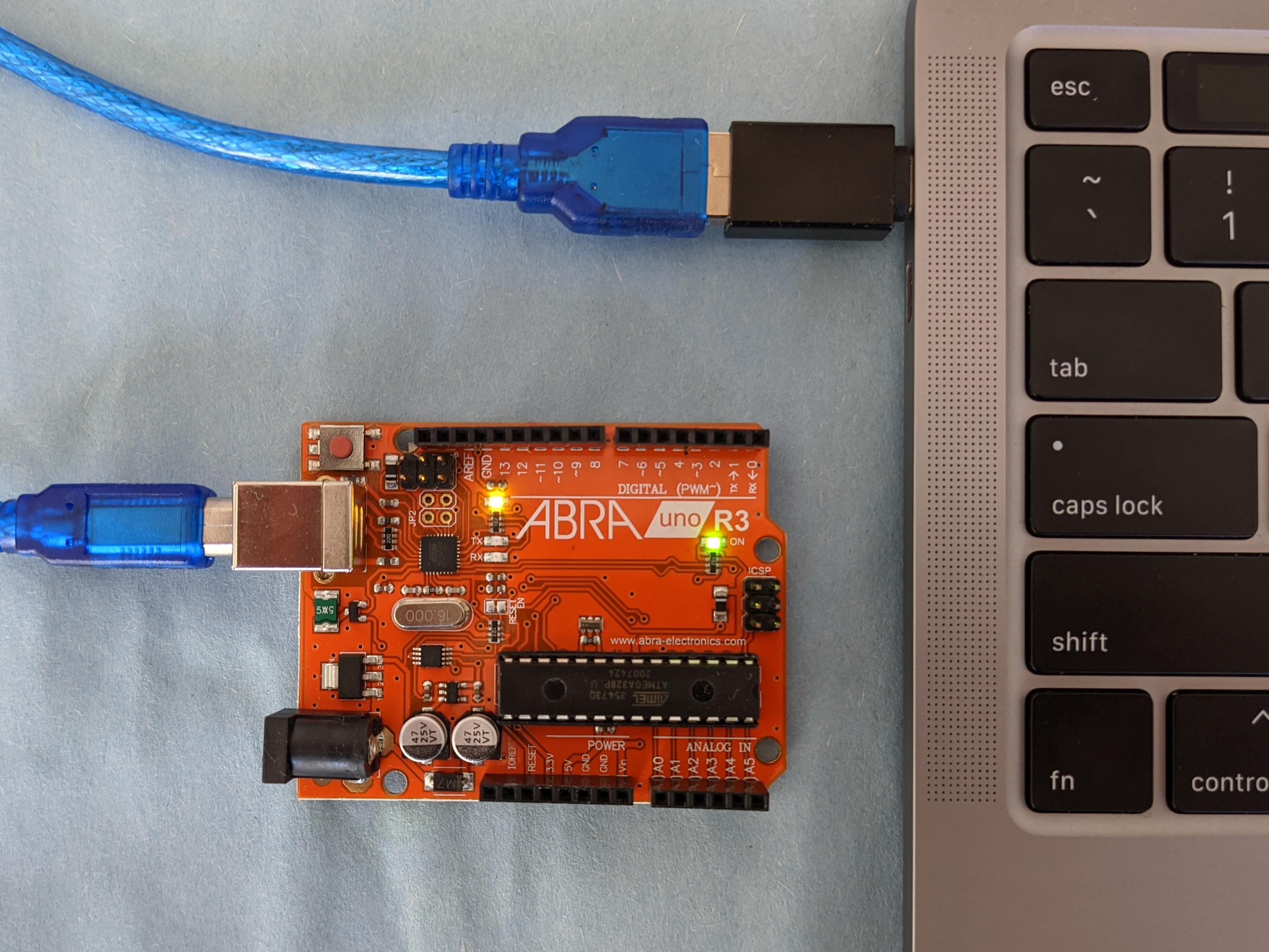
- Connect your laptop or desktop to the Uno via USB. To upload and run sketches your computer needs to know which board you are using and which port will be used for communication. From the dropdown menu select the correct board: Tools/Board/Arduino Uno. From the dropdown menu select the correct port which will differ from machine to machine: Tools/Port/"/dev/cu.name". A default "Blink" sketch may already loaded on the board.
Which port?
To know which port, you can look at which ports are available with your Uno disconnected. A new port will appear when you reconnect your board.
Open the "Blink" example in the IDE, from the dropdown menu: File/Examples/01.Basics. Change the 1000 millisecond delay to
delay(2000). Try to compile the program using the check mark icon. Upload to your board and run using the right arrow icon.If you have uploaded successfully the Uno board builtin LED near the GND and digital 13 pins will blink on and off with each state lasting two seconds.
Play around with different timing delays to see how you can control the built-in LED.
# Exercise 2: Move straight (virtual)
- Do the first Exercise in the Robot Lab: Move a Robot. Modify the sample sketch to collect all the coins. Hint:
rightservois not being used in the sample sketch.
# Exercise 3: Move straight (physical)
Goal: wire up the robot and test the servos using the Move a Robot example.
Take an inventory of all your hardware components.
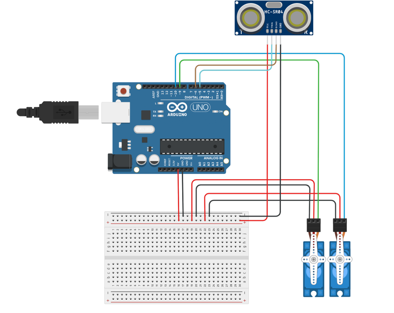
Connect only the servos to the Uno board using the schematic provided. The servos and ultrasonic sensor get 5V power and GND from the Uno board and also connect to digital pins for communication. Note that the 5V pin can be used for output or input voltage. In this case it used for output to the servos and the sensor through the breadboard.
Upload the working forward motion example to your Uno board.
Power your Uno Board using USB, AA batteries, a 9V battery, or by using a rechargeable power pack alternative (4$ example from Dollarama) and confirm the robot servos are working as expected. See note below on power. We will likely use power packs in this lab to keep things simple and consistent.
Try to get your robot moving in a straight line (one per table).
If you have accomplished this task before the end of lab, try modifying your code by using
nameservo.writecommands invoid loop.A look ahead: challenge yourself to write a move straight function and call it in the loop. Then try to write other functions like turnLeft, turnRight, or something more ambitious like zigZag.
# Basic Robot Build (starting from scratch)
Some important notes before constructing the robot
- Prepare to build on a large, clean surface.
- The servo wheels should be installed with care since it is easy to strip the screws.
- The leads of the jumper wires can be broken when connecting if handled too forcefully.
- Be careful not to lose the small hardware screws, nuts and bolts.
- Follow wiring schematic closely before powering.
Following the discussion in the video, build the robot chassis.
Powering the Uno board, servos and sensors
Power up the board using power supplied from your computer via USB cable or by using external power sources. The board can operate on an external supply from 6 to 20 volts. If supplied with less than 7V, however, the 5V pin may supply less than five volts. If using more than 12V, the voltage regulator may overheat and damage the board. The recommended range is 7 to 12 volts.The battery case provided takes 4 AA batteries providing ~5.5-6V. These notes refer to 4 suggested methods for powering the Arduino board. There are others.
- Power through USB from your computer. Proper voltage will be regulated out to servos and ultrasonic sensor through the 5V pin.
- Powering through the barrel jack: The battery pack with barrel jack connector provided in your kit, with normal alkaline batteries, will output ~6V. Proper voltage will be regulated out to servos and ultrasonic sensor through the 5V pin.
- It is also possible to power your board with a 9V battery, using a barrel jack connector.
- Recommended to be the cheapest and most reliable method for this project: rechargeable power pack 4$ Dollarama example can be purchased at Alexis Nihon.
← Post-lab 1 Pre-lab 3 →